Printed circuit boards (PCB) are embedded into almost all electronic devices. While a PCB is not necessarily needed to make an electronic system, they provide a convenient means of connecting various circuits together through copper routes while also providing a rigid and reliable surface to mount components on. The PCB can have a major impact on many electrical systems and thought should always be given to the choice of PCB material used.
Some key characteristics to consider when choosing a PCB material include the dielectric constant (Dk), dissipation factor (Df), thermal conductivity (TC), and coefficient of thermal expansion (CTE). Other key factors to examine are signal integrity, material cost, and manufacturing cost.
Materials covered in this guide can be found below. Click on a logo to jump to the material's section.
The dielectric constant is a number that represents a material's ability to store energy in an electric field. For PCBs, it impacts the velocity of propagation and the desirable trace thickness.
For example, lots of systems use traces that are designed to have a 50 Ohm impedance. Along with the dielectric thickness, the dielectric constant will also determine what trace thickness is needed to meet a 50 Ohm transmission line. Assuming a 10 mil dielectric thickness, a 50 Ohm trace width can be anywhere from 30 mils to 16 mils for a dielectric constant from 2 to 5.
The chart below visually shows this:
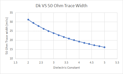
Figure 1. plot showing 50 Ohm trace thickness versus dielectric constant
Similarly, we can plot the propagation delay versus dielectric constant. This is shown in the plot below. Note that the propagation delay is shown in units of nanosecond per inch. This can be calculated by 11.8[inch/nSec] divided by the square root of dielectric constant. The 11.8[inch/nSec] is a constant that is the speed of light in a vacuum converted from its usual form shown in meters per second.
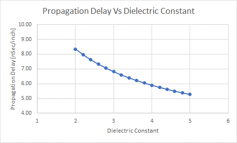
Figure 2.plot showing effect of dielectric constant on signal propagation velocity
Low Dk (Less than 4):
Low Dk materials are suitable for high-frequency applications such as microwave and RF circuits. These materials minimize signal loss and maintain signal integrity at high frequencies. Materials like PTFE (Polytetrafluoroethylene) fall into this category.
Medium Dk (Around 4 to 10):
Medium Dk materials strike a balance between high-frequency performance and cost. They are commonly used in applications like digital communication systems and microstrip transmission lines.
High Dk (Above 10):
High Dk materials are used for impedance matching and power amplifier circuits. They allow for tighter coupling of signals and are often used in high-speed digital designs.
The dissipation factor, also known as the loss tangent, tells a designer how lossy (electrical energy loss) a material may be. In other words, it defines the ability of an insulator to store energy. This is very important to consider when working with high speed digital circuits and RF circuits. Every PCB material will absorb some amount of energy when a signal is propagating through it. For a typical low cost FR4 material this number is usually on the order of 0.015.
Low Df (Less than 0.005):
Low Df materials are crucial for high-frequency applications where minimal signal loss is essential. They are often used in high-speed digital designs and high-frequency RF applications.
Medium Df (Around 0.005 to 0.02):
Medium Df materials offer a balance between electrical performance and cost. They are suitable for many general-purpose applications.
High Df (Above 0.02):
High Df materials are less common in PCB designs as they lead to significant signal loss. They might be used in applications where electrical performance is not the primary concern.
When loss and signal integrity are important, dissipation factor is a key parameter to seek out.
Thermal properties of PCBs can also be important to consider. This is especially true in high power applications where circuits may need to be sufficiently cooled to avoid performance degradation and ensure proper operation. It is generally represented by the letter “k” (sometimes TC) and is measured in units of [W/m*K]. Thermal conductivity describes how well a PCB can dissipate heat. Generally, a higher k value means more capability to transfer and dissipate heat. Of course, additional factors can come into play when dealing with heat dissipation in PCBs. This can include thermal vias, ground planes, and copper thickness.
Coefficient of thermal expansion (CTE) is also important to consider in large PCB structures. CTE is the rate of expansion of the PCB material as it changes temperature. It is generally measured in parts per million per degree Celsius [ppm/C]. This can be important to consider because the dielectric will have a different CTE than copper. As a result, over extreme temperature cycles it is possible that a via or trace can experience interconnect issues or complete failure.
Overall, PCB materials have many characteristics that are important to consider depending upon the given application. Additional characteristics exist which will not be discussed in detail here. These can include moisture absorption, mechanical strength, and flammability. Some of these properties may be required to meet a certain specification by institutions such as UL to be safe to use in consumer electronics.
Commonly Available PCB Materials Now that we have some knowledge around characteristics of PCB materials that can affect performance, we will review some commonly available materials. The first types of materials we will cover are FR4 materials. These are low cost general purpose PCB materials that are most commonly used
When comparing materials like Isola's 370HR, FR408HR, and Panasonic's Megtron series, the choice would depend on specific project requirements such as operating frequency, signal integrity, thermal considerations, and budget constraints.
Isola 370HR: This material is a medium-Dk (around 4.2) and low-Df (around 0.017) material. It strikes a balance between performance and cost, making it suitable for general-purpose applications and moderate-speed digital circuits.
Isola FR408HR: FR408HR is a high-performance material with a low Dk (around 3.66) and a low Df (around 0.008). It is good for high-speed digital designs and high-frequency applications where signal integrity is critical.
Panasonic Megtron Series: The Megtron series offers various materials with different Dk and Df values. These materials are designed for high-frequency applications, including advanced communication systems and high-speed digital designs.
While the specific characteristics of the materials from FR4 manufacturers can vary, they all feature the same attributes. FR4 has three different building blocks: copper, epoxy resin, and any number of woven fiberglass mat layers. The number of those layers ultimately determines the FR4’s thickness, where external copper layers can continue to be added if needed.
Other polyimide materials are not as complex or layered. Some flex PCB materials are created using two basic components, copper and a single layer of polymer plastic, while others can include a form of adhesive in between the layers. Rigid polyimide and other similar materials also often include glass reinforcement while their flex counterparts won’t.
Three notable categories for polyimide types in the United States are DuPont, LF, FR, & AP, though those categories themselves are often separated by adhesive and adhesive-less.
LF are acrylic-based laminates designed for basic jobs and products not requiring a UL safety rating and are free of Halogen. They can be purchased with the adhesive, without it, or combined with adhesive and copper on either side. Unfortunately, LF is not UL-approved due to its lower resistance to heat and intense temperatures.
FR is also acrylic-based and is designed to be fire retardant, making it UL-rated. There is FR adhesive as well as FR dielectric.
AP is an all-polyimide design with double-sided copper, it’s typically a flexible and high-performing material. While there are other high-speed, durable, and ultra-thin materials like TK, they require specialized processing. There is another adhesive-less material from DuPont called AC, which features 1 side of copper whereas FPCBs typically have 2 copper layers or more.
The key differences when it comes to material specifics all relate to the Dk values, the optimal operating temperatures, and the amount of moisture that can be absorbed by the PCB.
Typical rigid polyimide materials will feature a much higher temperature rating (Tg) - roughly 260° Celsius for polyimide and 170°-180° Celsius for high-temp FR4. Polyimide is also able to absorb roughly 20 times the amount of moisture that its FR4 counterparts can. Unfortunately, that moisture absorption does mean the PCB will require baking to ensure moisture doesn’t get trapped in any of the layers. Due to FR4 material's tendency to accrue 1% of moisture from the air, the PCBs need the baking process to ensure its removal.
Ventec International Group is a manufacturer that offers various PCB materials. Their VT-47 material is a low cost general purpose material. The dielectric constant of this material is typically 4.2. However, it has a maximum specification of 5.2. This means the impedance of traces routes can vary greatly. As a result, it may not be the best choice for applications that require controlled impedance routes. In addition, the loss tangent or dissipation factor is 0.016. This will not have much effect on low frequency applications or applications up to 1GHz. However, for applications that use high frequency signals above 1GHz the loss of VT-47 will begin to play a role in the overall performance of the circuits. Additionally, the thermal properties of the material are also in the bottommost range. The thermal conductivity has a typical value of 0.5[W/m*K], the Tg is 130C, and the CTE for Z-axis has a typical value of 45[ppm/C].
Isola is an additional company that offers a wide variety of PCB materials. Two similar materials they offer are FR406 and 370HR. These both offer higher performing thermal characteristics than a general purpose FR4. 370HR has a thermal conductivity of 0.4[W/m*K], a Tg of 180C, and a CTE for Z-axis of 45 [ppm/C]. The Dk is about 4.2 and Df is 0.016.
FR406 has a thermal conductivity of 0.4[W/m*K], a Tg of 170C, and a CTE of 60[ppm/C]. The Dk is 4 and Df is 0.013. The higher glass transition temperature of these materials means they can hold their mechanical structure better at higher temperatures. If a PCB is exposed to a temperature higher than its specified Tg, than it can lose its solid form. This can cause complete failure of an electrical system or product. However, short exposure to a higher temperature is generally ok. In fact, most reflow profiles exceed the Tg of PCBs. This generally will have little effect on the PCB as long as it is not repeatedly exposed to these higher temps.
Isola also offers a higher end FR4 material. One such material is FR408HR. This offers better electrical and thermal performance than the general purpose FR4 materials. Using a proprietary resin mixture, it achieves a better coefficient of thermal expansion and lower loss. This offers a great solution for applications where higher performance is needed but low cost may still be critical. For FR408HR the thermal conductivity is 0.4[W/m*K], the Tg is 190C, and the Z-axis CTE is 55[ppm/C]. Furthermore, the Dk is 3.7 and the Df 0.0091.
VT-901 Polyimide is a material that offers a rigid substrate that can withstand elevated process temperatures and is an optimal choice for high-heat and high reliability applications. Components and copper routes can be created on polyimide. Ventec offers a polyimide material known as VT-901. The Tg has a typical value of 250C and Z-axis CTE is 50[ppm/C]. The Dk of the material has a typical value of 4.1 and a maximum value of 5.4. In addition the Df is 0.012.
Isola also offers polyimide materials. The P95 and P96 materials are both polyimide based materials with very similar characteristics. Both materials have a thermal conductivity of 0.4[W/m*K], a Tg of 260C, and a Z-axis CTE of 55[ppm/C]. Also, the dielectric constant is 3.78 and dissipation factor is 0.0172 for both materials. The P95 material has a higher decomposition temperature (Td) which we have not previously discussed. This is the temperature in which a PCB chemically decomposes. Note that polyimide materials are generally higher cost and are generally used based on mechanical or size constraints. They do offer a higher Tg than FR4s however, they are generally worse at dissipating heat and are higher loss materials.
Rogers Corporation is a company known for developing high quality PCB materials. They are generally going to cost more than alternative PCB materials but offer high quality. They find most use in RF applications. This can include cellular systems and satellite communications. RF engineers also use these materials in high frequency applications to create filters or impedance matching structures using copper geometries.
One such series from Rogers is its RO3000 series which offers 4 different materials. The four materials offer different tiers of performance. For example, RO3003 has a thermal conductivity of 0.5[W/m*K] and a Z-axis CTE of 25[ppm/C]. The Dk is 3 and Df is 0.001. On the other hand, the RO3006 material they offer has a thermal conductivity of 0.79[W/m*K] and a Z-axis CTE of 24[ppm/C]. The Dk is 6.5 and Df is 0.002. Note that Z-axis CTE of these materials is the lowest found so far when compared to other materials covered. This suggests superior mechanical stability when compared to other materials.
An additional series offered by Rogers is its RO4000 series. Like the previously covered series this series offers higher performance characteristics such as lower loss. This series consists of two different materials. The first is RO4003C. This has a thermal conductivity of 0.71[W/m*K], a Tg of 280C, and a Z-axis CTE of 50[ppm/C]. The Dk is 3.66 and Df is 0.0031. The second material offered is RO4350B. This material has a thermal conductivity of 0.69[W/m*K], a Tg of 280C, and a Z-axis CTE of 50[ppm/C]. The dielectric constant is 3.55 and dissipation factor is 0.0021. Again these materials offer an excellent choice for applications requiring controlled impedance lines, low loss, and broadband operation.
Panasonic is a company probably best known for some of their consumer electronics. However, they also offer electrical components and even PCB materials. One such material is their Megtron6 series of materials. This material was designed for high frequency applications such as satellite communications. This product is most similar to the high quality offers of Rogers Corporation. The Tg of this material is 185C and the Z-axis CTE is [ppm/C]. Additionally, the dielectric constant is 3.4 and Df is 0.004.
The last materials that will be covered here are high quality offerings from Isola. Similar to the Rogers and Panasonic materials covered, these are designed specifically for higher frequency applications. As 5G technologies begin being implemented many of these higher quality and lower loss PCB materials found use in these applications. A couple higher quality offerings from Isola are their MT40 and MT77 materials. The MT40 material has a thermal conductivity of 0.61[W/m*K], a Tg of 200C, and a Z-axis CTE of 55[ppm/C]. The Dk is 3.4 and Df is 0.003. On the other hand, the MT77 material has a thermal conductivity of 0.45[W/m*K], a Tg of 200, and a Z-axis CTE of 20[ppm/C]. The Dk is 3.0 and Df is 0.0017. Note that these dissipation factors are an order of magnitude better than standard FR4 materials suggesting much lower loss.
Overall, we covered various types of PCB materials available from a few manufacturers. Depending upon a given application the designer must choose an optimal material. This can be dictated by thermal considerations, frequency of operation needed to support, cost constraints, or mechanical constraints. Always consult the manufacturer's datasheets and work closely with your PCB fabrication partner to select the most appropriate material for your project's needs.
To help compare the various types of materials available and the characteristics of each, the table below is offered. The cost of each material is not shown in the table as this can vary depending on panel size and PCB stack ups needed. However, it can generally be expected that the lower the dissipation factor, the higher the cost.
| Manufacturer | Material | Dk (1GHz) | Df (1GHz) | k (TC) [W/m*K] | CTE (Z-Axis) [ppm/C] | Tg [C] |
|---|---|---|---|---|---|---|
| Isola | 370HR | 4.17 | 0.0161 | 0.4 | 45 | 180 |
| Isola | FR406 | 3.95 | 0.0161 | 0.3-0.4 | 60 | 170 |
| Ventec | VT-47 | 4.27 | 0.016 | 0.5 | 45 | 180 |
| Isola | FR408HR | 3.69 | 0.0091 | 0.4 | 55 | 190 |
| Isola | Polymide P95 | 3.78 | 0.0172 | 0.4 | 55 | 260 |
| Isola | Polymide P96 | 3.78 | 0.0172 | 0.4 | 55 | 260 |
| Ventec | VT-901 | 4.05 | 0.012 | n/a | 50 | 250 |
| Rogers | RO4350B | 3.66 | 0.0031 | 0.69 | 50 | 280 |
| Rogers | RO4003C | 3.55 | 0.0021 | 0.71 | 40 | 280 |
| Rogers | RO3003 | 3 | 0.001 | 0.5 | 25 | |
| Rogers | RO3006 | 6.5 | 0.002 | 0.79 | 24 | |
| Panasonic | Megtron6 | 3.4 | 0.004 | 45 | 185 | |
| Isola | MT77 | 3 | 0.0017 | 0.45 | 50 | 200 |
| Isola | MT40 | 3.4 | 0.003 | 0.61 | 55 | 190 |
| Flexible Polyimide, Rigid Polyimide, and FR4 | Polyimide | 3.4 | 0.02 | 0.8 | 81 | 300 |
