A Metal Core Printed Circuit Board (MCPCB), also known as a thermal PCB or metal backed PCB, is a type of PCB that has a metal material as its base for the heat spreader portion of the board. The thick metal (almost always aluminum or copper) is covering 1 side of the PCB. Metal core can be in reference to the metal, being either in the middle somewhere or on the back of the board. The purpose of the core of an MCPCB is to redirect heat away from critical board components and to less crucial areas such as the metal heatsink backing or metallic core. Base metals in the MCPCB are used as an alternative to FR4 or CEM3 boards.
The metal core of the thermal PCB can be aluminum (an aluminum core PCB), copper (copper core PCB or heavy copper PCB) or a mixture of special alloys.
The most common is an aluminum core PCB. Other materials, like brass or steel, are sometimes considered but not recommended. These metals are very hard and cutting the PCB into smaller pieces can pose problems. Other considerations in selecting metal PCB materials are the chemicals in manufacturing and whether the metal will react to them.
The thickness of metal cores in PCB base plates is typically 30 mil - 125 mil, but thicker and thinner plates are possible.
MCPCB copper foil thickness can be 1 - 10 oz.
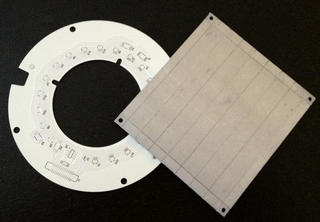
Metal Core PCB with Aluminum Core
MCPCBs can be advantageous to use for their ability to integrate a dielectric polymer layer with a high thermal conductivity for a lower thermal resistance.
Metal core PCBs transfer heat 8 to 9 times faster than FR4 PCBs. MCPCB laminates dissipate heat, keeping heat generating components cooler which results in increased performance and life.
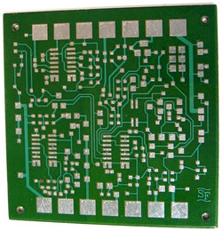
Heavy Copper Core PCB
Photo Credit: Robert Tarzwell
Applications that generate a large amount of heat often cannot be adequately cooled using just traditional fans. Conductive cooling through metal core PCBs are an ideal production option.
MCPCBs are most widely found in LED technologies, as they reduce the number of LEDs required to produce a specific illumination. Light emitting diodes release a great amount of heat in applications such as:
Using a metal core PCB in these LED products and applications help to greatly reduce the heat emitted.
Other applications that are ideal for MCPCB integration are solar panels and motion control applications. We also offer other advanced circuit technology including microwave RF PCB, flex PCB and rigid flex PCBs.
The manufacturing process and design rules are similar to conventional PCBs. We provide metal core pcb prototype fabrication and mcpcb fabrication quantities for both aluminum core and heavy copper PCBs.
Thermal management PCBs or MCPCBs are processed with standard SMT assembly equipment in the PCB manufacturing process.
Call us at 800.SFC.5143 or get an instant PCB quote.
We are ready and eager to turn your concepts into reality, from MCPCB manufacturing to assembly.
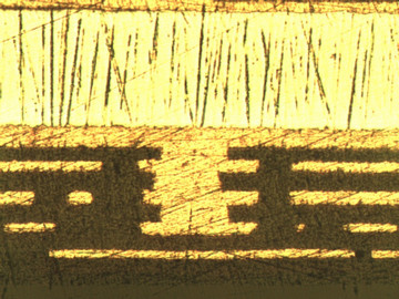
MCPCB - Close-up
Photo Credit: Robert Tarzwell
Too much heat stress can cause PCBs to function below optimal performance or even stop working entirely. Heat stress is one of the primary causes of failure in PCBs, and as technology has advanced, heat stress has, generally, increased due to components being placed together in a smaller form factor. This is exactly why effective thermal management in PCBs has become a critical factor in preventing a total loss of system functionality in electronic devices.
Thermal management is often accomplished through the use of a metal core using copper or aluminum, with the circuit layer and dielectric layers being stacked above it.
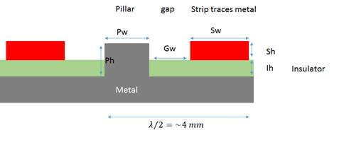
It is crucial to move heat away from heat-generating components to the external heat sink. Without proper thermal management, the performance of any application is at risk. Heat transfer improves when materials of high thermal conductivity like copper are used; and a copper pedestal provides a great solution. A copper based pedestal is an alternative technology that ultimately provides higher thermal conductivity for PCBs.
Copper used in the metal core pedestal improves thermal conductivity while reducing the working temperatures inside the component making it an ideal choice for reducing PCB heat stress.
Copper-based pedestals are used in the following situations:
Thermal management is critically important to PCB design as integrated and stacked components as well as miniaturization have increased the heat generated on these boards. Regardless of the choice of PCB substrate, PCB design layout and manufacturing processes, our team at San Francisco Circuits is able to help you get the right solution for any project.
